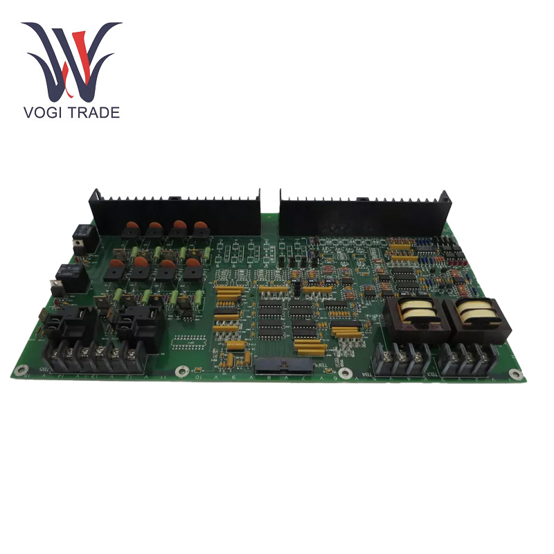
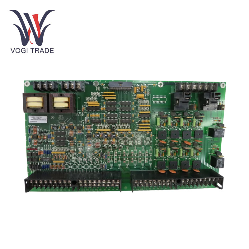
Brand: GE Description: LCI Auxiliary I/O Terminal Board Condition: Brand New Certificate: COO TEST REPORT WARRANTY LETTER Warranty: 1 year Inventory Qty: 7 Payment Term: T/T Shipping Port: ShenZhen GE DS200DDTBG2ABB is an LCI auxiliary I/O terminal board for managing auxiliary input and output signals. It supports high and low current inputs, voltage inputs, 4-20 mA current loops, and digital I/O, ensuring efficient signal processing and communication.
|
Manufacture |
GE |
|
Model Number |
DS200DDTBG2ABB |
|
Ordering Number |
DS200DDTBG2ABB |
|
Catalog |
Mark V |
|
Country Of Origin |
USA |
|
HS CODE |
8479909090 |
|
Dimension |
30cm*20cm*8cm |
|
Packing Dimension |
32cm*22cm*10cm |
|
Weight |
1.2kg |
Operating Parameters
Voltage Parameters: it can respond to 24 - 250 VDC / 24 - 230 VAC at 60 Hz, or 125 - 230 VAC at 50 Hz.
High Voltage AC Inputs: 2
High Current Signal Inputs: 6
Low Current Signal Inputs: 3
4-20 mA Current Loop Inputs: Up to 2
Undedicated Voltage Inputs: Available
Buffered Analog Outputs: 4
4-20 mA Current Outputs: 2
Digital Input/Outputs: 16
Voltage Parameters: it can respond to 24 - 250 VDC / 24 - 230 VAC at 60 Hz, or 125 - 230 VAC at 50 Hz.
Temperature Range: is 0 to 50 ºC.
Product Functions
I/O Signal Management: GE DS200DDTBG2ABB is a Load Commutated Inverter auxiliary I/O terminal board The mass employment of high - density connector ribbon cables to inter connect several other models means this is a major success. This allows the links to move any type of input and output signal from one component to another in the control system. It also connects to the DS200ADMA analog - to - digital option board in an LS2100 control system for auxiliary I/O signals.
Signal Conditioning and Isolation: The GE DS200DDTBG2ABB scales, buffers, conditions and isolates signals. This is useful since it translates the environment system - level signals into a format that can be understood by the system DSP. In the industrial environment, for instance, analog signals generated by various sensors will first require analog conditioning before they can be processed by the digital parts.
Multiple Input and Output Types:31 Digital Inputs and 33 Digital Outputs, 8 Analog Outputs Digital inputs can accept binary - state signals from switches or sensors, and digital outputs can drive relays and solenoids.Device connections are usually quite easy. 8 analog outputs used to provide continuous - variable signals for actuator control or for monitoring analog - type sensors.
Installation
Connector - based Connection: The GE DS200DDTBG2ABB has six connectors that each have different functions and methods of connection. 60 - pin high - density ribbon cable header TB5 connector is a 6 - position terminal strip and clamp TB3 and TB4 connectors are 3 - position terminal strips and clamps. These terminal - strip - type connectors are handy for making wire connections or connections to other compBindable parts that can be clamped in place. Thus, connectors TB1 and TB2 are 36 - position double - row connectors, so it attains a large amount of signals for certain subsystems.
Mounting Notes: The GE DS200DDTBG2ABB is intended for mounting to the back of a standard industrial control panel. It is likely that the component has mounting holes, slots, or similar features that enable it to be attached securely to the panel with screws or other suitable fasteners. This is to the effect that the board is stable and not prone to damage during operation due to improper mounting.
Application Range
Industrial Control Systems: Mostly used in LS2100 static starter control systems part of GE Mark V system. These individual control systems are widespread in industrial settings power plants, refineries, large - scale manufacturing facilities.to handle the operation of electrical motors, generators, and other high - power equipment.
Automation systems: The GE DS200DDTBG2ABB can be used to interface with various sensors, actuators, and other controllers to automate a manufacturing line regularly. For instance, it can also act as a receiver of signals from sensors, which may be used to monitor the position or the state of machinery parts, and a signal sender that transmits control signals to actuators to adjust the machinery operation.
Troubleshooting
Visual Inspection: Inspect the board for any visible signs of damage or defects, like burnt components or cracked traces.
Check Connections: Make sure that all ribbon cables and connectors are properly attached and not corroded.
Title: Jumper Switch SettingsObjective: To ensure that all jumper switches are properly aligned and configured as per factory settings or specific application requirements.
Signal testing: use the test points for signal integrity testing and to confirm that everything runs as expected.
LED Indicators: Check status LEDs for fault indications or abnormal status