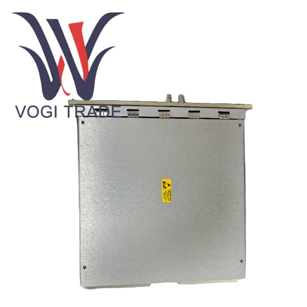
Brand: GE Description: TREA Turbine Emergency Trip Condition: Brand New Certificate: COO TEST REPORT WARRANTY LETTER Warranty: 1 year Inventory Qty: 7 Payment Term: T/T Shipping Port: Xiamen The IS200TREAH1AED Aeroderivative Turbine Emergency Trip (TREAHlA) terminal board works with PPRO turbine l/O packs as part of the Mark Vle system.
|
Manufacture |
GE |
|
Model Number |
IS200TREAH1AED |
|
Number of outputs |
2 trip contacts |
|
Catalog |
Mark VIe |
|
Contact ratings |
NEMA class F. Minimum operations: 100,000 |
|
HS CODE |
8538909100 |
|
Voltage |
28 V dc max |
|
Leakage |
2.21 mA max |
|
Weight |
2kg |
Product Overview
The IS200TREAH1AED Aeroderivative Turbine Emergency Trip (TREAH1A) terminal board works with PPRO turbine l/O packs as part of the Mark Vle system. The inputs and outputs are as follows:
For TMR systems, signals fan out to the JX1, JY1, and JZ1 DC-62 PPRO connectors.
TREAH#A cannot be used with the Mark Vl system.
Installation
For H1 and H2 board variants, voltage detection and the breaker relay are wired to the l/O terminal blocks TB1. Passive pulse rate pick-ups are wired to TB2. Each block is held down with two screws and has 24 terminals accepting up to #12 AWG wires. A shield termination strip attached to chassis ground is located immediately to the left of each terminal block.
For H3 and H4 board variants, voltage detection and the breaker relay are wired tothe l/O box terminals at the top of the board. Passive pulse rate pick-ups are wired to the lower terminals. All terminals plug into a header on the TREA board and accept up to a single #12 AWG wire.
Caution
The TREA must be configured for the desired speed input connections using the following table. Jumpers P1 and P2 select fanning of the X section pulse rate pickups to the Y and Z PPROS.
System Design:
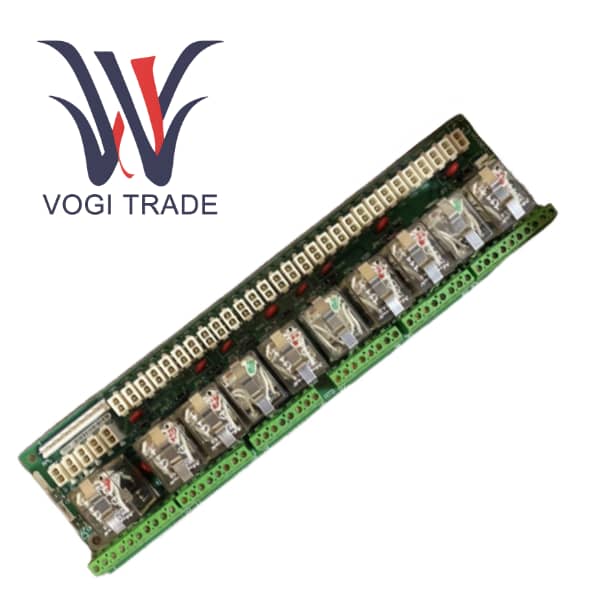
The IS200TREAH1AED board is designed using three PPRO l/O packs mounted directly on it. The TREA / PPRO assembly then forms a self-contained emergeney trip function.
TREAH1A, H2A, H3A, and H4A will only function correctly with three PPRO I/O packs. Simplex operation is not possible.
Speed Inputs:
When used with PPRO l/O packs mounted directly on the TREA the speed inputs provide two options. Each PPRO l/O pack may receive a dedicated set of three speed inputs from their respective TREA terminal points as is done on SPRO. As an option, jumpers P1 and P2 may be placed on the TREA to take the first three speed inputs (those for the X pack) and fan them to the Y and Z packs. When this is selected, the terminal board points for Y and Z. Speed inputs become no-connects and should not be used, As a check, the PPRO is configured for fanned or direct speed input and a feedback signal provided by TREA. If there is a mismatch between the jumper position and PPRO configuration, an alarm will be generated.
EStop:
The TREA includes an EStop function, This consists of an optically isolated input circuit designed for a de input in the range of 24 V to 125 V nominal. When energized, the circuit enables coil drive power in the X, Y, and Z relay circuits through independent hardware paths. The response time of this circuit of less than five milliseconds plus the response time of the trip relays ofless than one millisecond yields very fast EStop response. EStop is monitored by PPRO firmware, but the action to remove trip relay coil power is a hardware path in PPRO. It ispossible to configure PPRO to turn off the Estop function.
Voltage Monitors:
The trip relays on TREA may be freely located anywhere in a trip string. Because the trip string circuit is not fixed, there are three general-purpose isolated voltage sensor inputs on TREA. These may be used to monitor any points in the trip system and drive the voltage status into the system controller where action may be taken. Typical use of these inputs may be to sense the power supply voltage for the two trip strings (PWR) and to sense the solenoid voltage of the device being driven by the relays (SOL1, SOL2). This set of applications is used in the wording of the board symbol, but the sensors may be freely applied to best serve the application.
Contacts are polarity-sensitive, external voltage suppression MUST be used.