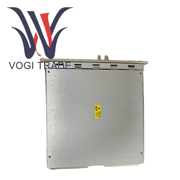
Brand: GE Description: simplex board with two DC-type connectors Condition: Brand New Certificate: COO TEST REPORT WARRANTY LETTER Warranty: 1 year Inventory Qty: 5 Payment Term: T/T Shipping Port: Xiamen GE IS200TRTDH1DBB is a dedicated 8-channel resistance temperature detector input terminal board designed by General Electric for Mark VIe and Mark VIeS turbines and process control systems. As a key component of the Mark VIe distributed I/O architecture, this board's core function is to provide a safe, reliable, and standardized physical wiring interface for on-site RTD temperature sensors.
|
Manufacture |
GE |
|
Model Number |
IS200TRTDH1DBB |
|
Ordering Number |
IS200TRTDH1DBB |
|
Catalog |
Mark VI |
|
Country Of Origin |
USA |
|
HS CODE |
8479909090 |
|
Dimension |
11.5cm*4.5cm*3.8cm |
|
Packing Dimension |
14*7cm*6cm |
|
Weight |
0.22kg |
Product Overview
The GE IS200TRTDH1DBB is a dedicated 8-channel resistance temperature detector input terminal board designed by General Electric for Mark VIe and Mark VIeS turbines and process control systems. As a key component of the Mark VIe distributed I/O architecture, this board's core function is to provide a safe, reliable, and standardized physical wiring interface for on-site RTD temperature sensors. The IS200TRTDH1DBB itself is an unpowered wiring hub that does not perform any signal processing. After the resistance signals from the on-site RTD sensors are connected to this terminal board via a shielded cable, they are then transmitted through a dedicated high-density ribbon cable to the PRTD I/O processor module installed on the control cabinet I/O rack. This design perfectly inherits and optimizes the high requirements for temperature monitoring in the Mark VI system, serving as the fundamental hardware for ensuring precise monitoring of key parameters such as bearing temperatures and winding temperatures of critical equipment like gas turbines and steam turbines.
Comparison of similar products
|
Characteristics |
GE IS200TRTDH1DBB |
Siemens SM331 RTD |
Emerson DeltaV M-Series RTD Card |
General RTD Acquisition Module |
|
Architectural concept |
Separate type |
Integrated / Semi-detached |
Separate type |
Integrated |
|
Core advantage |
Maximum maintainability, high reliability |
High integration, moderate cost |
Good maintainability, deep integration of DCS |
Flexible, low cost |
|
RTD connection |
Clearly support the 2/3/4 line system |
Usually supports 2/3/4-wire systems |
Usually supports 2/3/4-wire systems |
Depends on the specific model |
|
Maintaining convenience |
Extremely off-site operation |
Extremely off-site operation |
High terminal block is plug-in type |
Low Requires Unboxing |
|
Applicable platform |
GE Mark VIe/VIeS |
Siemens S7-300/400 |
Emerson DeltaV |
General-purpose PC/PLC |
|
Typical application |
Key equipment bearing/ winding temperatures of the power plant |
General Process Control |
Petroleum processing process control |
Laboratory, small project |
Installation Guide
Planning and Preparation
Confirm the required quantity of TTRTDH1DBB based on the I/O list
Install the 35mm DIN rail in the control cabinet
Place an order precisely for the corresponding length of GE-specific RTD strip cables
Mechanical Installation
Slide the IS200TRTDH1DBB into the DIN rail and secure it
Electrical Connection
System Side, Firmly insert both ends of the strip cable into the PRTD I/O module and the connector of the TTRTDH1DBB, and lock them.
Field Side, As an example of 3-wire system, connect the A wire of the RTD to the terminal RTD+.
Connect the B wire and C wire to the two RTD- terminals respectively.
Make sure that the resistances of the two compensation wires B and C are as consistent as possible, which is the key to the effectiveness of 3-wire compensation.
Connect the cable shielding layer and ground it at a single point in the cabinet.
Check and Power On
Carefully verify all connections, especially the A/B/C wires of the RTD.
After powering on, check through the ToolboxST software whether the readings of each channel of the PRTD module are normal and compare them with the actual measured temperature on site for verification.