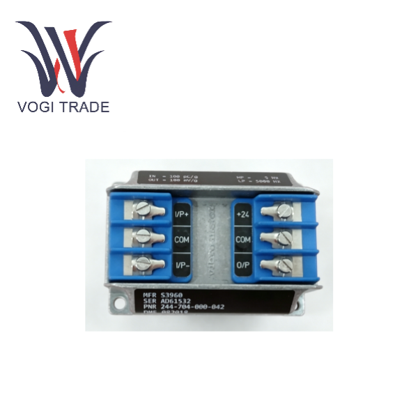
Brand: Vibro-Meter Description:Signal conditioner Condition: New Warranty: 1 year Inventory Qty: 1 Payment term: T/T Shipping Port: Xiamen The VIBRO IPC704 signal conditioner converts the chargebased signal from a piezoelectric-based transducer into a current or a voltage signal. This current or voltage signal is transmitted to the processing electronics via a standard 2-wire or 3-wire transmission cable.
|
Manufacture |
Vibro-Meter |
|
Model Number |
IPC704 |
|
Ordering Number |
244-704-000-032 A2-B07-C750-D1.45-E2-F20000-G0-H0-I0 |
|
Catalog |
Probes & Sensors |
|
Country Of Origin |
Switzerland |
|
HS CODE |
8537109090 |
|
Dimension |
26.2cm*12.5cm*2cm |
|
Packing Dimension |
28.2cm*14.5cm*4cm |
|
Weight |
0.3kg |
Product Overview
The Meggitt IPC704 is a high-performance signal conditioner specially designed for extreme environments and belongs to the Vibra-Meter product line. This device is mainly used to convert the weak charge signals output by piezoelectric accelerometers and dynamic pressure sensors into stable 2-wire current or 3-wire voltage signals, supporting long-distance transmission up to 1 kilometer to ensure accurate and reliable data. IPC704 244-704-000-032 features excellent environmental adaptability, with an operating temperature range of -30℃ to +85℃. It also offers an industrial housing option with an IP66 protection rating, which can resist the invasion of dust, oil stains and water jets. The product has passed multiple international explosion-proof certifications such as IECEx, ATEX, and cCSAus, and is suitable for hazardous areas in the chemical and energy industries. It is equipped with a built-in configurable high/low pass filter and an optional integrator, which can effectively eliminate noise interference and achieve the conversion of acceleration to velocity signals. It is an ideal choice for the condition monitoring and protection of turbine machinery.
FEATURES
From the Vibro-Mleter product line
For CAxxx piezoelectric accelerometers and CPxxx dynamic pressure sensors
Configurable high-pass and low-pass filters
Frequency range: 0.5 Hz to 20 kHz
Optional integrator to produce a velocity output
Optional 2-wire current or 3-wire voltage transmission
Certified for use in potentially explosive atmospheres
A range of installation options are available
Problems encountered during use (FAQ)
Problem 1, Abnormal signal output.
Cause: Incorrect sensor type identification. The IPC704 has different versions for standard piezoelectric materials and GaPO₄ materials; mixing them will lead to sensitivity mismatch.
Problem 2, Explosion-proof certification expired.
Cause: When selecting non-spark protection (Ex nA), the user must ensure that the device is installed in an enclosure with at least IP54 protection rating; otherwise, it does not meet explosion-proof specifications.
Problem 3, Long-distance transmission interference.
Cause: During dynamic pressure transmission or long-distance transmission, the GSI isolation unit was not used, causing common-mode interference to affect the readings.
Installation Guide
Selection confirmation
Confirm whether the sensor type is standard piezoelectric or GaPO₄ and select the corresponding IPC704 version.
Installation method selection
DIN rail installation: Use MA130 adapter. Wall-mounted installation: Fix with M4 standard version screws or M6 industrial housing version screws.
Wiring
Input terminal: Connect the piezoelectric sensor (symmetrical or asymmetrical).
Output terminals: 2-wire (+24V and COM) or 3-wire (+24V, COM, Signal). Explosion-proof precautions: If the Ex nA (non-spark) version is used, it must be installed in a sealed box of IP54 or higher grade. Ensure that the specification of the cable introduction device (grand head) matches the diameter of the cable, such as ∅4-∅ 7mm or ∅7-∅ 11mm. Debugging: Set the output range according to the sensor's sensitivity and configure the high and low pass filters as per application requirements.