Brand: Vibro-Meter Description:Proximity Transducer Condition: New Warranty: 1 year Inventory Qty: 1 Payment term: T/T Shipping Port: Xiamen The Vibro-Meter IPC704 is a dedicated and high-performance machine protection card designed by the Swiss Vibro-Meter company for its flagship VM600 series of condition monitoring and protection systems. The model 244-704-000-042 A3-B03-C100-D77-E2-F5000-G0-H0-I0 is a fully configured order number. As the core protection component of the VM600 system, IPC704 is not used for routine condition monitoring data analysis, but is dedicated to executing high-speed and deterministic protection logic.
|
Manufacture |
Vibro-Meter |
|
Model Number |
IPC704 |
|
Ordering Number |
244-704-000-042 A3-B03-C100-D77-E2-F5000-G0-H0-I0 |
|
Catalog |
Probes & Sensors |
|
Country Of Origin |
Switzerland |
|
HS CODE |
8537109090 |
|
Dimension |
26.2cm*12.5cm*2cm |
|
Packing Dimension |
28.2cm*14.5cm*4cm |
|
Weight |
0.3kg |
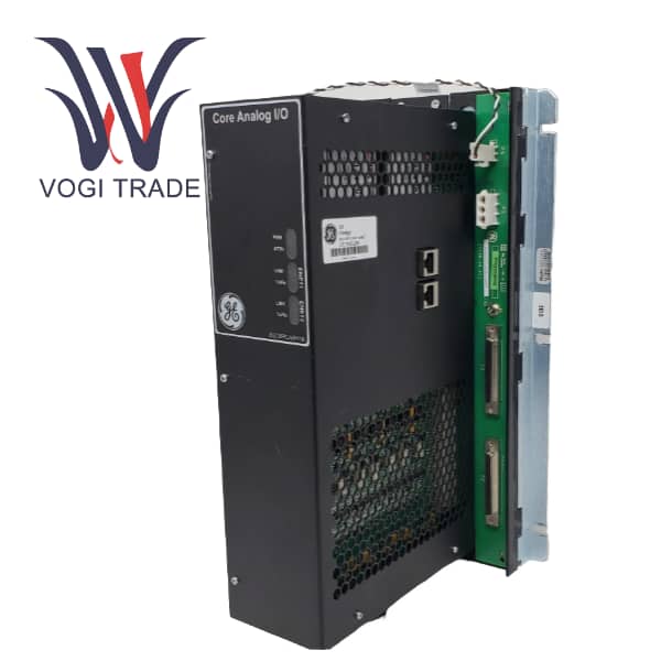
Product Overview
The Vibro-Meter IPC704 is a dedicated and high-performance machine protection card designed by the Swiss Vibro-Meter company for its flagship VM600 series of condition monitoring and protection systems. The model 244-704-000-042 A3-B03-C100-D77-E2-F5000-G0-H0-I0 is a fully configured order number. Here, 244-704-000-042 is the base model, while the suffixes A3-B03-C100... precisely specify its hardware and software functionality set. As the core protection component of the VM600 system, IPC704 is not used for routine condition monitoring data analysis, but is dedicated to executing high-speed and deterministic protection logic.
Related Product Recommendations
Complementary hardware
VM600 VME chassis
IOC700 series interface/conditioning module provides power supply, buffering and EMC protection for sensors
CPU M module used for system management and communication
Complementary software
Meggitt API670 Configuration Software - dedicated protection card configuration and testing software
Vibro-Meter 501 software - used for overall system monitoring and viewing alarm and waveform data of IPC704 Sensor
Vibro-Meter Electromagnetic Wave Probe and Preamplifier
Vibro-Meter Velocity Sensor
Installation Guide
System Preparation:
Prepare the VM600 VME chassis, CPU M module, IOC700 interface module, and IPC704 card.
Install and authorize the API670 Configuration Software.
Hardware Installation
Power-off operation: When the VME chassis is completely powered off, carefully insert the IPC704 card into the designated slot on the VME backplane and fix it with a bracket.
Use the dedicated flat cable to connect the IOC700 module to the IPC704 card.
Connect sensors: Connect the cables of the vibration, displacement, etc. sensors to the corresponding terminals of the IOC700. Ensure the probe installation gap is correct.
Connect the trip circuit: Connect the ESD input circuit to the SSR relay output terminal of the IPC704. This wiring must be completed by a qualified electrical engineer and follow all safety regulations.
Power-on and Configuration
Power on the VME chassis.
Open the API670 Configuration Software and establish communication with the IPC704 via RS-485.
Channel configuration: Set the sensor type, range, and engineering unit for each channel.
Protection logic configuration: Set the alarm thresholds, delay time, suppression conditions, and voting logic for Alert and Danger.
Waveform recording configuration: Set the sampling rate and recording length.
Download Configuration: To the IPC704. Functional testing
Before the machine is put into operation, each protection channel and each relay output of IPC704 must undergo a complete functional test in accordance with the requirements of API 670.
The testing methods usually include injecting simulated signals or using dedicated test instruments to verify whether the entire link from the signal input to the relay action is working properly, and record the test results for audit purposes.