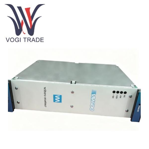
Brand: Vibro-Meter Description: Rack Power Supply Condition:New Certificate:COO TEST REPORT WARRANTY LETTER Warranty:1 year Inventory Qty:8 Payment term:T/T Shipping Port:Xiamen The Meggitt RPS6U 200-582-915-034 rack power suppliesare designed for use in the VM600Mk2/VM600 series of machinery protection systems and condition and perfommance monitoring systems, from Meggitt's vibro-meter product line.
|
Manufacture |
Vibro-Meter |
|
Model Number |
RPS6U |
|
Ordering Number |
200-582-915-034 |
|
Catalog |
rack power supply |
|
Country Of Origin |
Switzerland |
|
Humidity |
5 to 90%, non-condensing |
|
Drop test |
30° drop angle |
|
Vibration |
10 to 55 Hz, 0.35 mm peak below resonance and 2 g peak above, 6 hours/axis |
|
Weight |
0.8kg |
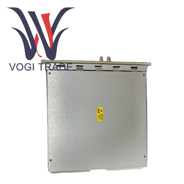
Product Overview
RPS6U is a 6U standard rack-mounted power module, belonging to the core component of the Vibo-meter product line. It is specifically designed to supply power to the Meggitt VM600 series mechanical equipment protection system, equipment status and performance monitoring system rack (ABE04x). The 200-582-915-034 is a dedicated back panel that matches the AC input version of the RPS6U. It is responsible for external mains power connection, branch power supply, switch/fuse protection, and wiring transfer. The combination of the two forms a complete power supply system for the VM600 rack. A single VM600 rack (ABE04x) can accommodate up to two RPS6U power modules, occupying 15 to 17 slots (PS2) and 18 to 20 slots (PS1) at the front of the rack respectively. When paired with the 200-582-915-034 backplane, both RPS6Us are of AC input type, and the backplane has two independent AC power supply circuits.
Core Functions
RPS6U Power Module Core Functions:
1. Rack-Mounted Centralized Power Supply: Converts external AC power to +5V and ±12V DC voltages compatible with the VM600 board, providing unified power to all monitoring cards, data acquisition cards, and communication cards via the rack backplane. It is the core power source for the entire VM600 system.
2. Multiple Safety Protections: Integrates overvoltage, overcurrent, and continuous short-circuit protection, preventing damage to backend boards in case of failure. Wide temperature range design ensures stable operation in high and low temperature industrial environments with minimal power derating.
3. Redundant Power Supply Support: Supports hot backup redundancy when dual modules are connected in parallel: If one RPS6U unit fails, loses power, or is damaged, the other automatically takes over 100% of the load, ensuring uninterrupted operation and no data loss for the mechanical equipment monitoring system, improving the reliability of continuous operation of industrial equipment.
Multiple Safety Protections: In case of failure, power outage, or damage to one RPS6U unit, the other automatically takes over 100% of the load.
200-582-915-034 Rear Panel Core Functions:
1. Dual AC Independent Inputs
Provides two physically isolated AC input terminals, allowing connection to two different AC power sources. This achieves external AC power redundancy, preventing system shutdown due to a single AC power outage.
2. Branch Protection and Control
Each AC circuit is independently configured with a switch, fuse, and EMI filter circuit. A fault in one circuit will not affect the normal operation of the other, facilitating individual troubleshooting and power-off maintenance.
3. Signal Monitoring and Alarms
Built-in power detection relay, linked to rack panel indicator lights, outputs real-time power status signals, allowing maintenance personnel to quickly diagnose power supply faults.
4. Cabinet Transfer
Serves as a rear rack cabling hub, transferring external AC power to the front RPS6U power module, organizing rack cabling and meeting industrial cabinet wiring specifications.
Hardware Installation Steps
1. Rack Preparation
Use a standard 19-inch industrial rack to secure the VM600 rack (ABE04x), ensuring good rack ventilation ,operating temperature ≤65℃, unobstructed surroundings.
2. Back Panel Installation
Push the 200-582-915-034 back panel into the corresponding slot from the rear of the rack and tighten the screws; confirm that the back panel contacts reliably align with the rack back panel.
3. RPS6U Power Module Installation
Insert two RPS6U AC modules from the front of the rack, securing them in slots 15-17 (PS2) and 18-20 (PS1) respectively, and lock them in place, ensuring full contact between the front connectors and the back panel.
4. External Wiring
Two sets of AC terminal blocks on the back panel (L live wire, N neutral wire, PE ground wire) are connected to two independent AC mains power supplies respectively;
Strictly distinguish between phase wires, neutral wires, and protective ground, and ensure reliable grounding (PE terminal must not be left floating);
Each circuit has an independent operating switch, and the switch should be kept in the open position after wiring is completed.
5. Powering on the Unit
Close the two AC circuit switches in sequence and observe the power indicator light on the rear of the frame: constantly lit = normal power supply, flashing/off = circuit fault.
Wiring Specifications
1. Wire Requirements: Industrial multi-strand copper core wire, compatible with terminal block crimping specifications, crimped cold-pressed terminals, avoid bare wire contact;
2. Grounding Requirements: The system protective ground must be connected to the factory's equipotential grounding network, with a grounding resistance <4Ω, improving anti-interference and safety performance;
3. Circuit Differentiation: PS1 and PS2 AC circuits must not be connected in parallel or in series, and must remain physically independent.
Operational Prohibitions and Safety Precautions:
1. It is strictly forbidden to connect the AC input RPS6U to a DC high voltage source. It is strictly forbidden to connect the DC input power supply to this AC backplane.
2. It is strictly forbidden to cover the module's heat dissipation vents. The operating ambient temperature must not exceed +65℃.
3. It is forbidden to plug or unplug the RPS6U module from the backplane while it is powered on; both AC switches must be disconnected first.
4. If the module experiences a continuous short-circuit protection failure, do not repeatedly force power on; first check for short-circuit faults on the back-end boards.
5. The backplane fuse is of original factory specification; do not replace it with a fuse of higher current, otherwise the protection will be lost.