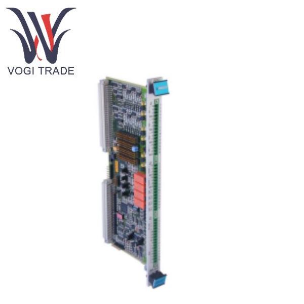
Brand: Vibro-Meter Description: Input/Output card Condition:New Certificate:COO TEST REPORT WARRANTY LETTER Warranty:1 year Inventory Qty:8 Payment term:T/T Shipping Port:Xiamen The IOC4T 200-560-000-018 is a dedicated signal interface I/O board card of the Vibro-Meter series from Meggitt, which is used in conjunction with the MPC4 unit protection card of the VM600 system. It is a hot-swappable rear-mounted module for the VM600 rack and must be used in pairs with the MPC4 unit protection card
|
Manufacture |
Vibro-Meter |
|
Model Number |
VM600 IOC4T |
|
Ordering Number |
200-560-000-018 |
|
Catalog |
Input/Output card |
|
Country Of Origin |
Switzerland |
|
Humidity |
0 to 90%, non-condensing |
|
Temperature |
−25 to 65°C (−13 to 149°F) |
|
Vibration approvals |
IEC 60255-21-1 (Class 2) |
|
Weight |
0.25 kg, 0.55lb |
Product Overview
The IOC4T 200-560-000-018 must be used in pairs with the MPC4 unit protection card, installed directly behind the MPC4 card, and communicate with the MPC4 through the IP industrial packet interface.
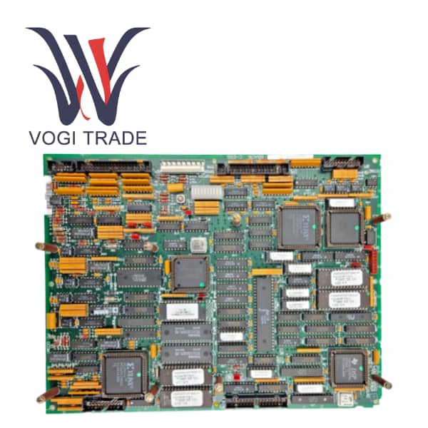
The product is available in two hardware versions: standard type and isolation loop type. It can be optionally coated with a three-proof coating to enhance its tolerance to harsh environments. The entire board card integrates EMI electromagnetic interference protection for input and output, meeting EMC electromagnetic compatibility standards. It supports hot plugging and unplugging. Its functions cover vibration dynamic signals, speed key signal access, analog quantity transmission output, local relay alarm, extended digital alarm output, external hard contact control, etc. The overall safety integrity level of the machine is SIL1. It is widely used in the protection and condition monitoring of industrial rotating machinery.
Product Use
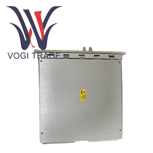
The IOC4T 200-560-000-018 is installed in the VM600 rack (ABE04x standard rack/ABE056 ultra-thin rack). The back panel is equipped with 3 sets of 16-position screw terminal blocks J1/J2/J3, and all sensors and external control system wiring are connected through the terminals. It is powered by the back plate of the rack + 5V and ±12V, with low power consumption of the whole machine and a physical size of 6U height
Practical application case
Condition monitoring of compressors on offshore platforms
For reciprocating compressors on offshore oil and gas platforms, in environments with high humidity and salt spray, the IOC4T type with three-proof coating isolation circuit is selected.
Question 1: Can the IOC4T be used independently without the MPC4 card?
Answer: No. The IOC4T is a slave I/O interface card; it lacks signal processing or alarm logic capabilities and serves solely as a companion signal interface for the MPC4 machinery protection card. It must be installed in the same rack slot as the MPC4—positioned directly behind it—and communicates with the MPC4 via the IP industrial packet bus. All data acquisition, alarm processing, and output logic are controlled by the MPC4 card, so the IOC4T cannot operate independently.
Question 2: How do I switch the IOC4T analog outputs between 4–20 mA and 0–10 V, and what are the limitations?
Answer: Each analog output channel is equipped with an independent hardware jumper; the output type for a specific channel is selected by adjusting the jumper position. The four channels can be configured individually for voltage or current output, without requiring a uniform output mode across all channels.
Limitations: For current output, the downstream load resistance must be less than 325 Ω to avoid signal distortion; for voltage output, the load impedance must be greater than 100 kΩ. The actual driving range for current output is 2–23 mA, with 0 mA and 24 mA corresponding to sensor wire-break and over-range faults, respectively, facilitating system-level anomaly detection.