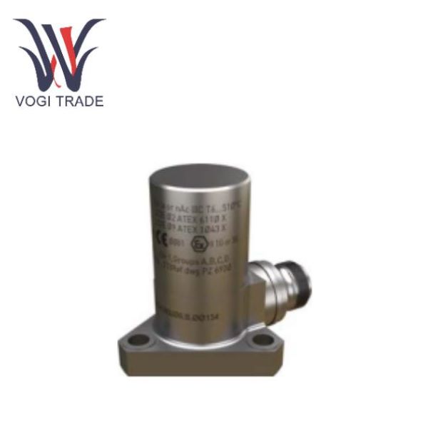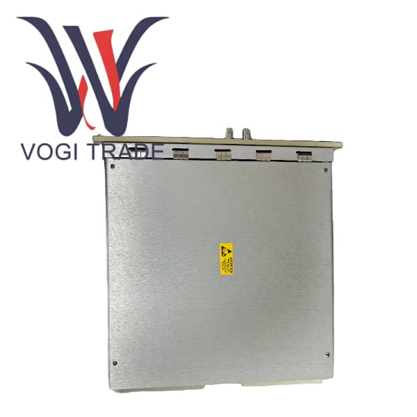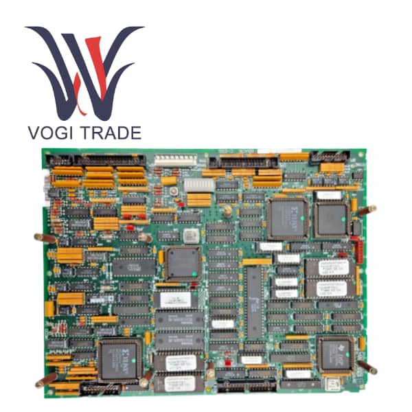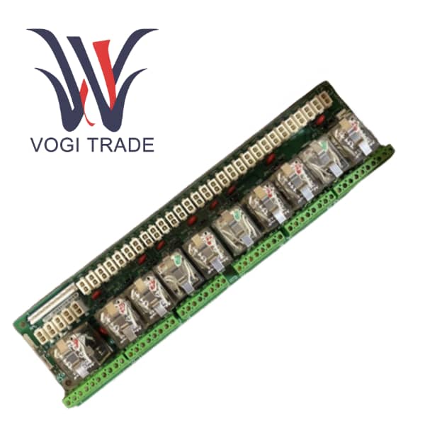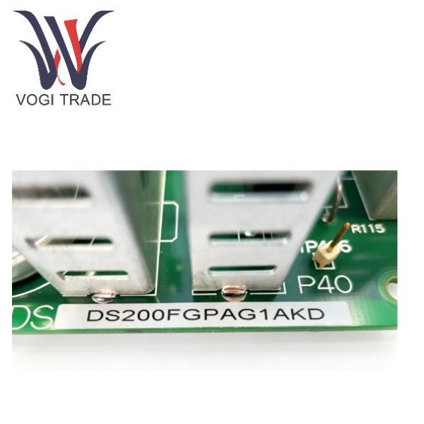
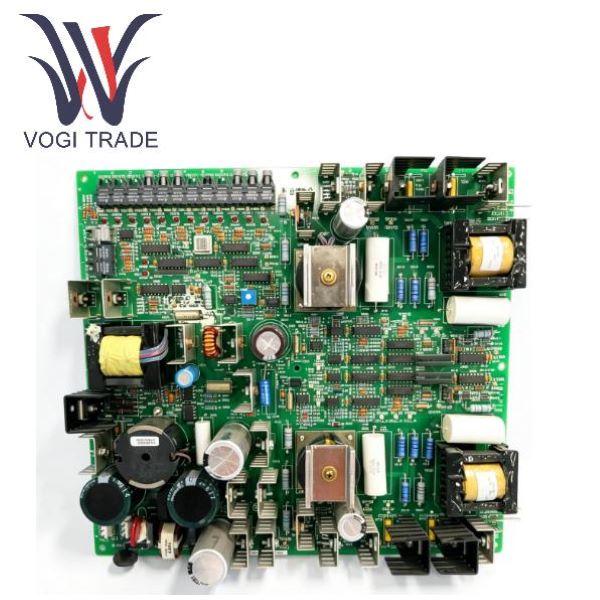
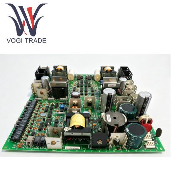
Brand: GE Description: Gate Pulse Amplifier Condition: Brand New Certificate: COO TEST REPORT WARRANTY LETTER Warranty: 1 year Inventory Qty: 4 Payment Term: T/T Shipping Port: Xiamen The GE DS200FGPAG1AKD (FGPA Gate Pulse Amplifier Board) is a key interface board for the high-power power conversion loop of the GE SPEEDTRONIC Mark V control system, centered around Mark V TMR triple redundancy, SIFT software voting, and full-link diagnosis
The DS200FGPAG1AKD is a gate pulse amplifier board of the GE DS200 series. It is a dedicated power interface board for the SPEEDTRONIC™ Mark V gas turbine/steam turbine control system, mainly serving the static starting device of the LS2100 LCI unit and the generator excitation rectification system. This board card receives the optical fiber trigger pulse issued by the Mark V three-redundant R/S/T controller, drives the high-power SCR thyristor after isolation amplification, and simultaneously collects the operation fault signal of the rectifier device in real time and transmits it back to the main control. The DS200FGPAG1AKD adopts the optical fiber electrical isolation design, is compatible with the 125V DC standard power supply for the cabinet, and fully complies with the Mark V TMR redundancy, SIFT software voting and whole machine diagnosis specifications. Relying on the built-in diagnostic function of the system, board-level faults can be accurately located. The TMR model supports online replacement of single board cards, and fault information can be stored in a 1ms precision SOE event log, effectively avoiding false tripping of the unit caused by single-point failure of the power circuit. It is the core expansion hardware for power conversion control of thermal power gas turbines
|
Manufacture |
GE |
|
Model Number |
DS200FGPAG1AKD |
|
Ordering Number |
Gate Pulse Amplifier |
|
Catalog |
Mark V |
|
Country Of Origin |
United States (US) |
|
HS CODE |
9032899099 |
|
Dimension |
20*16*6cm |
|
Weight |
0.8kg |
Three core hardware functions
1. Gate Pulse Drive Amplifier:
The DS200FGPAG1AKD receives the weak fiber optic trigger pulse from the Mark V controller. The onboard FPGA circuit amplifies it to a sufficient drive current to trigger the three-phase SCR rectifier bridge.
Each FPGA corresponds to one set of three-phase thyristor bridges. The entire LCI starter requires three DS200FGPAG1AKD units to fully cover the three-phase fully controlled rectifier topology.
It is compatible with Mark V servo/power output standards: the output pulse timing is strictly synchronized with the 62.5ms control frame period of the R/S/T triple-redundant controller.
2. Onboard Isolated Switching Power Supply:
Input is taken from the Mark V cabinet's 125V DC system power distribution bus: the system's standard DC power supply is 100~144V DC.
It is isolated and converted to a dedicated DC power supply for the onboard FPGA, fiber optic transceiver, and gate drive circuit.
It has a built-in voltage diagnostic circuit; when the power supply is abnormal, it reports the fault to the upstream R/S/T controller, triggering the Mark V's built-in diagnostic alarm.
3. SCR Thyristor Status Monitoring and Fault Feedback:
Real-time acquisition of the conduction, short circuit, open circuit, and overcurrent status of each SCR;
The DS200FGPAG1AKD transmits fault signals back to the Mark V triple-redundant controller via 15 fiber optic interfaces; Faults participate in Mark V software voting SIFT logic: the median value of the power circuit status received from the three R/S/T channels is used for judgment; a single-channel board fault will not trigger a false trip of the unit, but only generates a diagnostic alarm; Alarm data is stored in the Mark V event log (Log Functions), supporting 1ms precision SOE timing recording and trip waveform recording (Trip Log can store up to 63 sets of unit parameters).
The working logic under the TMR three-redundancy architecture
The Mark V core fault-tolerance mechanism is a triple modular redundancy TMR+SIFT software voting system. The DS200FGPAG1AKD operates within this system as follows:
Typical application scenarios
Scenario 1: Gas Turbine LS2100 LCI Static Start System
Function: Drives the rotor to accelerate to ignition speed when the unit is stationary, replacing the traditional starter motor;
Supporting Logic: Mark V R/S/T controller outputs start-up timing pulses → DS200FGPAG1AKD amplifies and drives the LCI rectifier-inverter bridge;
Multi-Unit Control: Multi-unit control, sequential control logic (Application Software ladder diagram programming). The start-up timing can be modified online and downloaded to EEPROM without stopping the unit.
Scenario 2: Steam Turbine Generator Excitation Regulation System
Function: Regulates generator excitation current, stabilizes terminal voltage, and controls reactive power;
Supporting Logic: Mark V acquires analog voltage and current signals from PT/CT (Hardware I/O supports 6 PT and 3 CT AC inputs), calculates excitation output commands, and drives the excitation rectifier bridge via the FGPA board;
Synchronization Interlocking: Works with the Mark V automatic synchronization module (<P> protection module has built-in 25P/25X synchronization logic) to accurately regulate voltage and frequency synchronization before grid connection.
Related Product Recommendations
IS220UCSAH1A
IS215VCMIH2CB
IS200VCMIH2CAA
300-LINE CONTROL CR306J1**
IS420UCSCH1ADS200DDTBG2ABB
CA4005B24D H41014(DS3800XTFP1E1C)
IS200DSPXH1DBD
IS200EACFG2ABC
IS200EPCTG1AAA
IS200EDCFG1AED
IS200EXAMG1AAB
IS200EPDMG1BAA
DS200FHVAG1ADA
DS200FCSAG2ACB
DS200FCSAG1ACB
DS200FGPAG1AKD