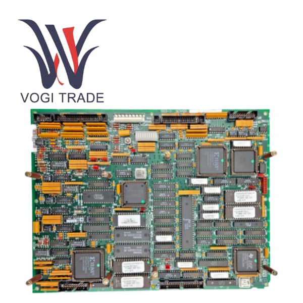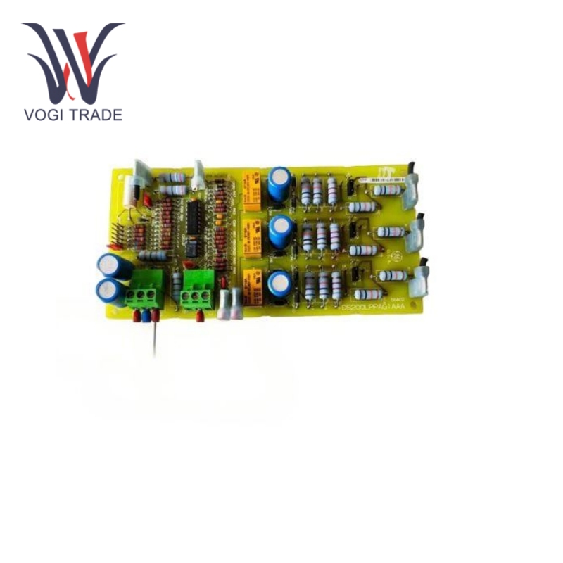
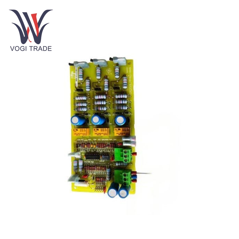
Brand: GE Description: Line Protection Card Condition: Brand New Certificate:COO TEST REPORT WARRANTY LETTER Warranty: 1 year Inventory Qty: 12 Payment Term: T/T Shipping Port: ShenZhen GE DS200LPPAG1AAA is a line protection panel. It is designed to protect wires, equipment, and personnel from faults, overloads, short circuits, and electrical interference. It features jumpers and terminal blocks for safe connections and includes test points for diagnostics.
|
Manufacture |
GE |
|
Model Number |
DS200LPPAG1AAA |
|
Ordering Number |
DS200LPPAG1AAA |
|
Catalog |
Mark V |
|
Country Of Origin |
USA |
|
HS CODE |
85389091 |
|
Dimension |
18cm x 7cm x 1.9cm |
|
Packing Dimension |
21cm x 10cm x 4cm |
|
Weight |
0.4kg |
Operating Parameters
Input Voltage: Designed for use with industrial voltage levels (200-600 VAC).
Power Supply Voltage: Requires a 28 V DC power supply.
Operating Temperature Range: Functions within a temperature range of 40°C to 85°C.
Mounting Type: Front mounting on the chassis.
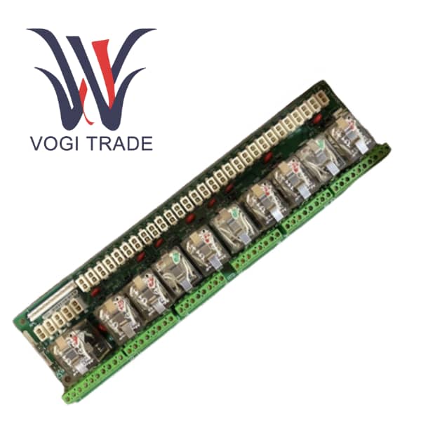
Connectors: Features 7 jumpers (JP1 through JP7) and 2 terminal blocks (3 terminals each) for secure connections.
Product Features
Precision Signal Processing: GE DS200LPPAG1AAA Equipped with advanced signal processing chips, it can accurately analyze and process various types of signals. This is especially useful in applications that require high-fidelity results. like those in audio and video processing contexts. In the case of multimedia production studios, it can enhance the quality of recorded images and sounds.
Multiple I/O Options: GE DS200LPPAG1AAA comes with a wide range of input and output ports. Digital I/O ports are capable of being connected to devices including sensors and controllers, whereas analog I/O ports are able to read continuous signal inputs provided by sensors. This versatility lets it adjust to various technical environments.
Fault resilience: The built-in redundancy and self-healing mechanism ensure that the device will keep running in case of minor faults. In the event of a failure component, GE DS200LPPAG1AAA may enable reroute signals automatically, actuate backup systems, reduce standstill, and maintains the integrity of the whole system.
Installation
Mechanical Installation: The product includes a mounting kit. It should be secured solidly on a flat, vibration-free surface with provided screws and brackets. Ensuring proper alignment is vital to avoid any stress on internal connectors and components. In applications or environments with a high level of vibration, more vibration-dampening measures should be employed.
Power Cord Connection: Make sure to connect the power cord to the correct power source according to the wiring instruction. Be careful with polarity or it may cause damage. Signal cables: Fit into corresponding I/O ports on the device and connected device. As soon as you’ve connected, do a visual check of all cables to see that they’re properly seated and not damaged.
Configuration Setup: Once installed, you would go to a configuration interface, typically available via dedicated software or a web-based portal. Input required parameters like device address, baud rate of communication (if any) and the operating mode. Such customization allows the device to be uniquely suited to the needs of the application, maximizing performance.
Application Range
Automotive Testing: Automotive testing can be employed in the automotive domain to conduct component testing and analysis. GE DS200LPPAG1AAA will receive information from sensors affixed to the engine, transmission and brakes, allowing the unit to analyze data for quality control as well as performance.
Integrating medical devices: GE DS200LPPAG1AAA helps integrate various medical devices in a clinic or hospital setting. It is capable of orchestrating the flow of data between devices such as patient monitors, imaging devices, and infusion pumps to ensure patient care is delivered effectively.
Industrial Control Systems: GE DS200LPPAG1AAA can assist in monitoring and controlling multiple production processes in factories. It can also receive signals from temperature sensors, pressure gauges, and flow meters, and send control commands to actuators to maintain optimal operation.
Troubleshooting
Power supply issues: If the device doesn’t turn on, check the power cable for obvious signs of damage or any loose connections. Make sure the power supply is outputting the right voltage. Then, if the cable is fine and a suitable voltage is present, look at the internal power supply for damage, such as a blown fuse or a failed capacitor.
Trouble in signal transmission: In case there is some trouble occurring in transmission of data or signal, check the cable connection at both ends. Inspect the I/O ports for any damage or blockage. Finally, verify that the communication settings comply with those of the attached device. For wireless communications, verify signal strength and interference.
Irregular functioning: Check the software failures if the device acts weird or provide an inaccurate output. Restart the device and reload the configuration. If the issue continues, it could point to an actual hardware failure. Look for any overheating, loose connections or issue with the internal chips.