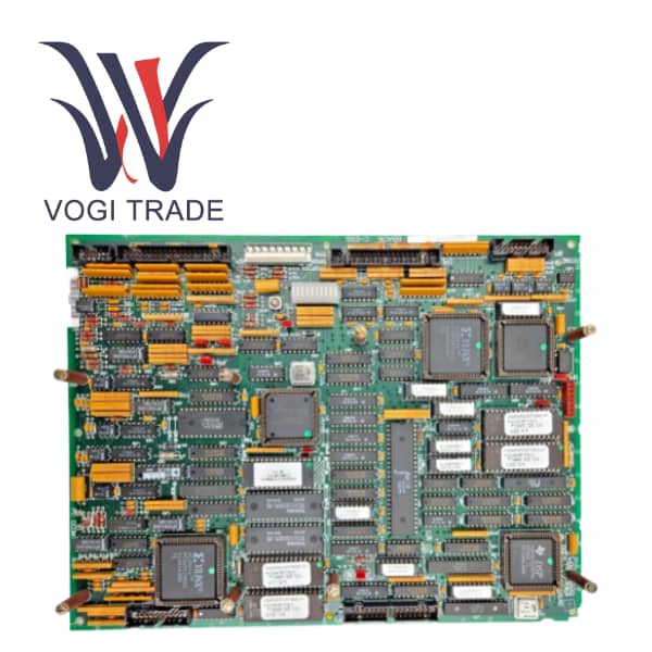
Brand: GE Description: Bridge Personality Interface Board Condition: Brand New Certificate: COO TEST REPORT WARRANTY LETTER Warranty: 1 year Inventory Qty: 10 Payment Term: T/T Shipping Port: ShenZhen GE IS200BPIAG1AEB is a bridge personality interface board designed for the GE Mark VI turbine control system.Key functions include processing gate driver and shunt fault signals, phase sensing, and data storage via a 1024-bit memory device for board identification and diagnostics.
|
Manufacture |
GE |
|
Model Number |
IS200BPIAG1AEB |
|
Ordering Number |
IS200BPIAG1AEB |
|
Catalog |
Mark VI |
|
Country Of Origin |
USA |
|
HS CODE |
8479909090 |
|
Dimension |
35cm*35cm*5cm |
|
Packing Dimension |
37cm*37cm*7cm |
|
Weight |
1.2kg |
Operation Parameters
Power Supply Voltage: 5V DC
Input and Output Sensitivity: Handles gate drive, shunt fault signals, and application data from the BPIA board
Operating Temperature Range: -15°C to +55°C
Protection Level: Industrial-grade protection; static-sensitive, requiring careful handling
Connectors: Various connectors for signal and phase connections, including 6 male vertical pin connectors and stab-on connectors for DC link and phase sensing signals
Additional Features: Includes 1024-bit memory, various electronic components like transistors and resistors
Product Features
System Interface: The card acts as a bridge between the BPIA/BPIB TYPE connected to Innovation Series Drive while offering communication and addressing the needs of the turbine.
Signal Handling: The GE IS200BPIAG1AEB manages gate drive signals, shunt fault signals and application data to and from the BPIA board.
I/O: The board provides phase sensing signals, DC link positive and negative signals It functions on voltage signals, current signals, fault signals and many other such signals.
Connectors:Six male vertical pin connectors for phase A, B and C IGBT connections. Five stab-on connectors to sense phase A, B, C, and DC link (+), (-) signals.
1024-bit Memory Device: GE IS200BPIAG1AEB also has a 1024-bit serial memory device that stores board ID and revision information. This assists with maintenance and troubleshooting to identify the card.
Primary Connector: The board connects to to the VME rack using this connector.
Other Connectors: Besides, the GE IS200BPIAG1AEB has a total of seven connectors on the board that includes gate drive and sensing signal pins.
Key Components: This card features three transformers, six transistors and nine resistor network arrays, constituting the signal handling and system control functions.
Static-Sensitive: GE IS200BPIAG1AEB is a static-sensitive board, which can be damaged by electrostatic discharge (ESD) and therefore should be handled with care. So good grounding, and handling precautions during the installation & maintenance are required.
Industrial Protection:Patented Industrial Protection Industrial Protection system specialized for the control of turbines in power generation plants.
Installation
Slot Compatibility:This GE IS200BPIAG1AEB is often installed in a VME rack in a designated slot for interfaces between the CS3000 system and other devices.
Identification: The board has a faceplate with labels and ID markings to make installation easier.
Application range
Industrial Automation: GE IS200BPIAG1AEB is used on a large scale to control production lines in factories. It can oversee the functions of conveyor belts, robotic arms, and machining tools, improving efficiency and product quality.
Power Generation: Possible Applications include controlling generator turbines, voltage regulators, and power plants in the power supply system. That helps guarantee stable power generation and delivery to the grid.
Oil and Gas: It guides pumps, compressors, and valves in refineries and on drilling platforms. It is capable of operating in extreme conditions, including high-pressure and dangerous, corrosive, or explosive environments.
Troubleshooting
LED Indicators:Check the IMOK LED for operational status. If the LED is off or flashing, there may be a communication or power issue.
Connection Integrity: Ensure all connectors, including P1 and stab-on connectors, are tight and not damaged.
Power Supply: Make sure that the board is fed by the right 5V DC power supply.
Signal Verification:Verify SignalTraverse through the diagnostics to ensure that signal transmission and reception between the control system and the drive is correct.
Memory Test: Verify 1024 bit memorydevice is functioning correctly. Faults that require replacement of a board are usually indicated by corrupt or inaccessible data.
Environmental Factors: Verify the board is functioning within optimal environmental conditions, for temperature and humidity, for example.