Brand: GE Description: Exciter Backplane Control Board Condition: Brand New Certificate: COO TEST REPORT WARRANTY LETTER Warranty: 1 year Inventory Qty: 7 Payment Term: T/T Shipping Port: ShenZhen GE IS200EBKPG1CAA is a control interface board designed primarily for industrial automation and turbine control applications. It facilitates communication between field devices and central control systems by processing digital signals and providing feedback for efficient control.
|
Manufacture |
GE |
|
Model Number |
IS200EBKPG1CAA |
|
Ordering Number |
IS200EBKPG1CAA |
|
Catalog |
EX2100 |
|
Country Of Origin |
USA |
|
HS CODE |
8479909090 |
|
Dimension |
40cm*20cm*8cm |
|
Packing Dimension |
42cm*22cm*10cm |
|
Weight |
1.2kg |
Operation Parameters
Power Supply: 24 VDC or 125 VDC.
Operating Conditions: −40 °C to +70 °C.
Protection: Short Circuit, Overload, Overvoltage, Reverse Polarity.
Communication: Allows integration into control systems through support for Modbus RTU/ASCII and other GE proprietary protocols.
Digital Outputs: This type of module has digital output signals used to drive external devices such as relays, solenoids, or actuators.
Common Voltage Range: Input from 10 VDC to 30 VDC
Typical Output Voltage: 24 VDC.
Product Features
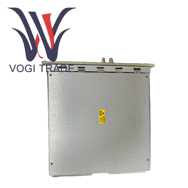
Backplane and Connector Function: The backplane provides a physical and electrical pathway for the control boards, allowing the I/O terminal board cables to connect to the I/O devices through connectors, forming the basis for communication between the various control boards and I/O devices.
Test Point Provision: Includes three sets of test points (M1, M2, and C), which can be useful diagnostic tools for allowing technicians to monitor and analyze system performance.
Exciter Gate Pulse Amplifier Interface: This interface consists of six connectors that serve as the interface points for up to six EGPA boards that are intended to be controlled by the ESEL board.
Signal Conversion and Conditioning: The GE IS200EBKPG1CAA converts the signals from the field (e.g., temperature, pressure, flow rate) from the sensors to data so they can be used by the control system.
Digital Control: GE IS200EBKPG1CAA is used to generate binary signals to control external devices such as relays, actuators, and motors to enable precise automation in turbine and industrial systems.
Data Monitoring and Feedback: Continuously monitors input from the field devices and provides feedback to the control system. This allows operators to view real-time system performance and adjust as required.
Fault Detection and Diagnostics: GE IS200EBKPG1CAA can detect and transmit diagnostic information on faults in the attached sensors or devices to the control system. This enables the detection of problems before they lead to failures across the system.
Integration with GE Control Systems: The GE IS200EBKPG1CAA pairs effortlessly with the GE Speedtronic suite of products allowing customers to build and maintain a comprehensive control architecture for complex systems like gas turbines.
Installation
Rack Mounting: the board is safely fitted in a rack with the collection of control boards.
Connector Installation: Its upper part adopts DIN connectors to connect to the plug-in control boards while its lower part adopts D-sub connectors used for connecting I/O interface cables. Lock connectors in place as you install them to form secure electrical connections.
Fan: Two cooling fans installed at the top of the rack for ventilation.
Application Range
used chiefly: in GE EX2100 excitation system, which used it to provide an orderly means for control boards and cables to be connected to one another, accounting for an essential component in the excitation system's control module. GE IS200EBKPG1CAA can be used for different industrial equipment and systems with excitation control including generators motors and other rotating equipments.
Troubleshooting
Module Won't Initialize:Verify power supply connections. Verify proper voltage (either 24 VDC or 125 VDC) is delivered and in the permitted range.
Communication Failures: In the case there is a communication failure between the module and central control system, check the communication line wiring (RS-232, RS-485, etc.)
Overheat:Make sure that the module is installed in a well-ventilated environment, and that the temperature does not exceed the specified operating range (-40°C ~ +70°C).
Relay Output Problems: Use a multimeter to test the relay output and see if it is functioning properly.