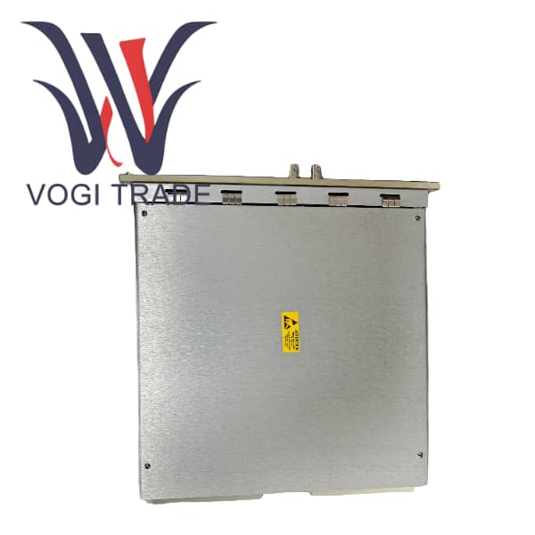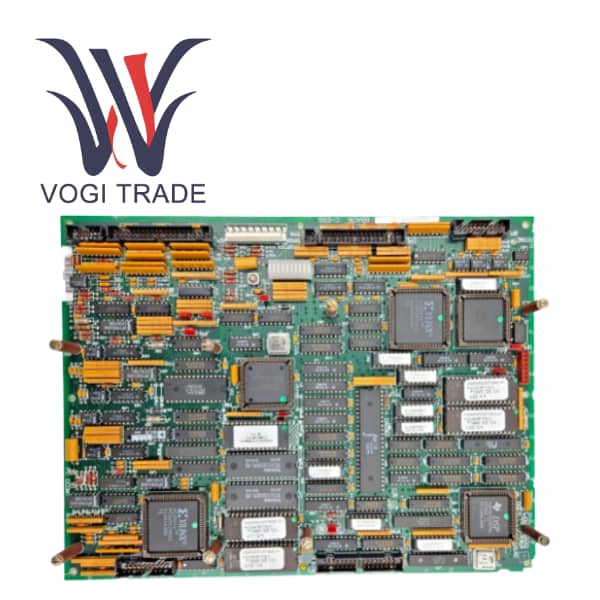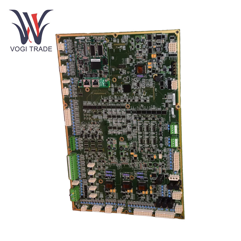
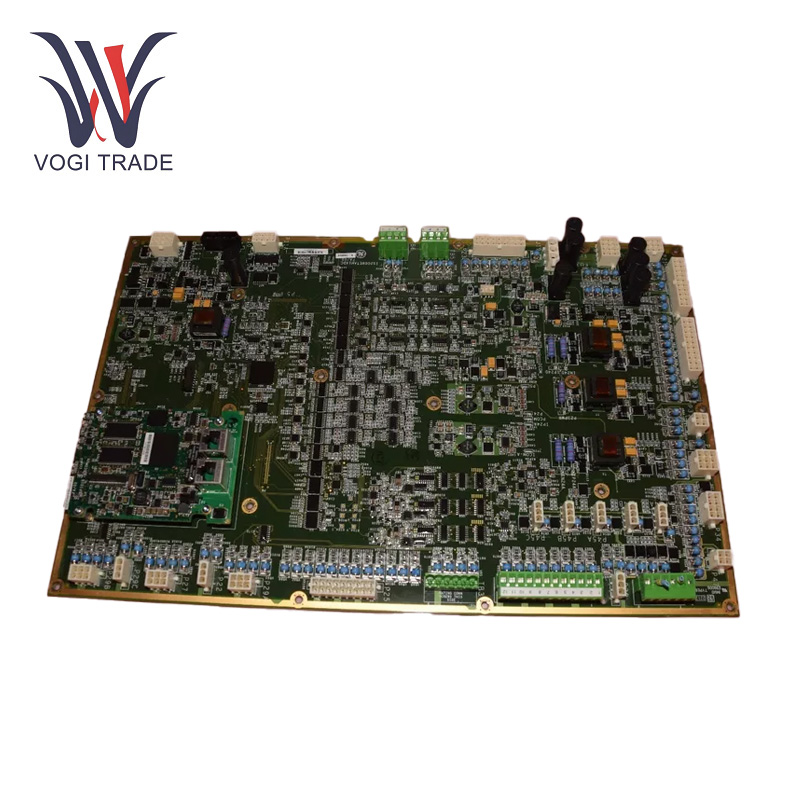
Brand: GE Description: Printed Circuit Board Condition: Brand New Certificate: COO TEST REPORT WARRANTY LETTER Warranty: 1 year Inventory Qty: 7 Payment Term: T/T Shipping Port: ShenZhen GE IS210BPPBH2CAA is a printed circuit board designed for the Mark VI turbine control system. It plays a key role in turbine control and monitoring by processing input signals and facilitating communication between system components.
|
Manufacture |
GE |
|
Model Number |
IS210BPPBH2CAA |
|
Ordering Number |
IS210BPPBH2CAA |
|
Catalog |
Mark VI |
|
Country Of Origin |
USA |
|
HS CODE |
8479909090 |
|
Dimension |
40cm*35cm*5cm |
|
Packing Dimension |
42cm*37cm*7cm |
|
Weight |
1.2kg |
Operating Parameters
Input Voltage: 24V DC
Operating Temperature: -40°C to +85°C
Compatibility: Designed for use with both steam and gas turbines as prime movers within the Mark VI system.
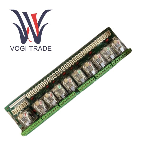
Connectors: Equipped with eight female plug connectors, with pin counts ranging from two to eighteen.
Protective Components: Features six metal oxide varistors on the left side of the board for surge protection.
Environmental Specifications: Operates within a humidity range of 5% to 95% .
Product Features
Generating Control Signals with High Precision: It is mainly responsible for the generation of extremely precise control signals. GE IS210BPPBH2CAA takes this signal and converts it into a signal that can physically modulate the operation of connected devices and reads input from various sensors and higher level control systems. In a power generation scenario for example, it can adjust the fuel injection rate of a turbine according to the metrics of performance in real time.
Communication Interface: The GE IS210BPPBH2CAA is an advanced communication interface designed for high-performance connectivity. It may use industry standard protocol like Ethernet or serial communication to communicate with other modules in the same system. This allows it to share sensor readings, status updates, and control commands, promoting better coordination between various components.
Fault Detection and Isolation: Internal diagnostic features enable it to constantly monitor its operation and those of peripheral devices. If an abnormality is identified, for example on a short circuit or an out-of-range signal GE IS210BPPBH2CAA can quickly pinpoint the source of the problem and isolate the area affected. The prognostics avoid small problems from turning into critical failures.
Installation
Physical Mounting: Start with the physical mounting. Make sure that it is clear from any blockage or dirt. The equipment is usually built to be attached to a conventional DIN rail or a flat surface using suitable mounting brackets and screws. Make sure you line it up correctly and lock it into place to prevent shifting around while running, as that can break connections or degrade performance.
Wiring Connections: Connect power supply and signal cables using the supplied wiring diagrams exactly. Be vigilant in terms of wire colors and pin assignments to prevent wiring errors. The connectors and terminals used in this type of assembly need to be of the highest quality to ensure a reliable electrical connection. Use the recommended procedures to strip the wire ends to proper length and crimp or solder the connections.
Configuration and Calibration: After physical installation, certain parameters may need to be configured and the device calibrated. These include configuring communication addresses, defining signal scale factors, initializing diagnostic features, etc.
Application range
Power Generation Plants: Control and maintain proper operation of gas and steam turbines for electricity generation.
Oil and Gas Industry: GE IS210BPPBH2CAA Use in controlling turbines used in extraction and processing operations.
Industrial Automation: GE IS210BPPBH2CAA Used in automated control systems for process industries such as oil and gas, chemical, and manufacturing.Overseeing turbine-driven machinery to maintain operational integrity.
Diagnostic Systems: Provides real-time monitoring and diagnostics for preventive maintenance.
Protection Systems: Acts as a critical component in turbine protection systems to prevent damage during abnormal conditions.
Troubleshooting
Signal loss or degradation: Caused primarily due to loose connectivity or faulty sensors. To fix this problem, check wiring and sensor operation.
Unexpected System Behavior: May be caused by incorrect configuration settings or component malfunctions. Review system settings and test components to identify and rectify the problem.
Communication Failures: May arise from faults in the VME backplane connection or from interference. Make sure your board is firmly seated and look for sources of electrical noise.