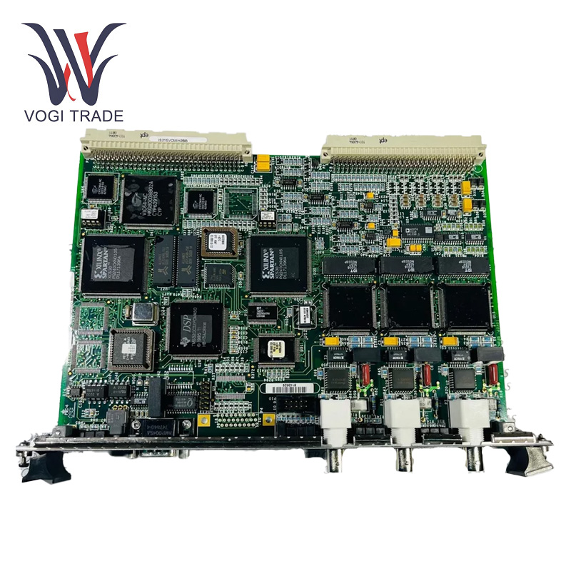
Brand: GE Description: VME Communication Interface Card Condition: Brand New Certificate: COO TEST REPORT WARRANTY LETTER Warranty: 1 year Inventory Qty: 15 Payment Term: T/T Shipping Port: ShenZhen GE IS215VCMIH2B is a VME communications interface board used in the Mark VIe turbine control system. It facilitates seamless communication between system components, enabling the transfer of control signals and operating data.
|
Manufacture |
GE |
|
Model Number |
IS215VCMIH2B IS200VCMIH2B |
|
Ordering Number |
IS215VCMIH2B IS200VCMIH2B |
|
Catalog |
Mark VI |
|
Country Of Origin |
USA |
|
HS CODE |
8479909090 |
|
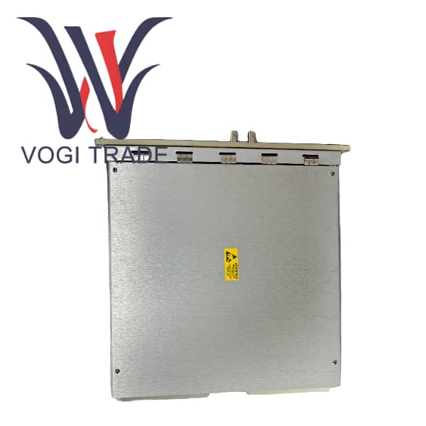
Dimension |
40cm*35cm*5cm |
|
Packing Dimension |
42cm*37cm*7cm |
|
Weight |
1.2kg |
Operational Parameters
Power Supply: 24V DC power supply.
Operating Temperature Range: -40°C to 70°C.
Humidity range for operation is 5% - 95% non condensing.
Signal Processing: It serves as an interface for communication between the system’s central processing unit and peripheral devices, facilitating the transmission of control signals, feedback data, and other essential operational information.
Product Features
Data Acquisition and Processing: One of the core functions of the GE IS215VCMIH2B is data acquisition. This module has an internal analog to digital converter that translates these analog signals into digital data. Once the data is acquired, it not only processes it, but also performs various enhancing operations, like filtering, scaling, or calibration to make sure the data aligns.
Control and Monitoring: GE IS215VCMIH2B is possible to implement control functions in the module based on processed data. It can check the measured values against preset thresholds and initiate appropriate actions. It also enables real - time system parameter monitoring so that the status of the connected equipment can be monitored by operators.
Communication Hub: Communication Hub The GE IS215VCMIH2B communication hub is the main communication interface in the turbine control system, responsible for transmitting data between system modules and peripheral devices.
Control Signal Relay: The board facilitates the accurate transfer of essential control signals, sensor feedback, and operational data to both the central control system and other connected modules.
Diagnostics and Monitoring: The board has diagnostic capabilities that can offer feedback in real time about communication performance and system health. It assists in identifying communications errors or hardware problems that could affect the control of the turbine.
Protocol translation: It supports several communication protocols, allowing seamless integration with various system components, sensors, and controllers within the turbine system.
Installation
Preparation: Before going for installation switch off the power supply of the whole system completely to avoid electrical shock a well as damage to module. Before you begin, make sure you have all the required tools including screwdrivers, cable strippers, and crimping tools.
Mounting: The GE IS215VCMIH2B can be installed for panel - mount. Choose a proper location on the control panel away from heat, humidity and electromagnetic interference sources. Fasten the module to the panel with the supplied holes and screws Remember to keep the module level and securely fastened so no vibration occurs while in operation.
Wiring the Sensors: Connect the sensors to the input terminals of the module. This will make it less vulnerable to interference. Check that the sensor connections are snug and secure.Connect the Ethernet cables to the Ethernet ports on the module. You can use Cat 5 or above category cables for good communication. As mission-critical elements, be mindful of how they are configured on the network and properly terminate the cables.
Application range
Power Generation: In power generation plants, safe and efficient operation of turbines relies on effective exchange of data and control, which is where it comes into play.
Genus industrial automation: Another application in industrial automation systems that require real-time communication and automated control, such as chemical plants, oil refineries or manufacturing facilities.
Troubleshooting
Power Generation: Begin with a visual analysis of the board for any noticeable damage, such as burnt components, loose connections, or physical wear. Make sure all the connectors are properly seated
LED Indicators: The GE IS215VCMIH2B is provided with LED indicators for the operational status of the board. Examine these LEDs to determine whether there are any communications problems or power problems.
Range Check: Validate both incoming and outgoing signals are in range. Signal transmission errors might indicate hardware problems or incorrect connections.
Jumper settings and Configuration review: Make sure that all jumper settings and configuration parameters are configured properly as per your system requirement. Please note that erroneous setup might lead to communication errors or system instability.
Operating System Diagnostics: invoking system diagnostics or using diagnostic softwarechecks could reveal any system errors or malfunctions that may be hindering communication.