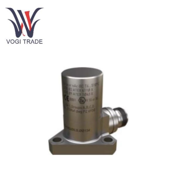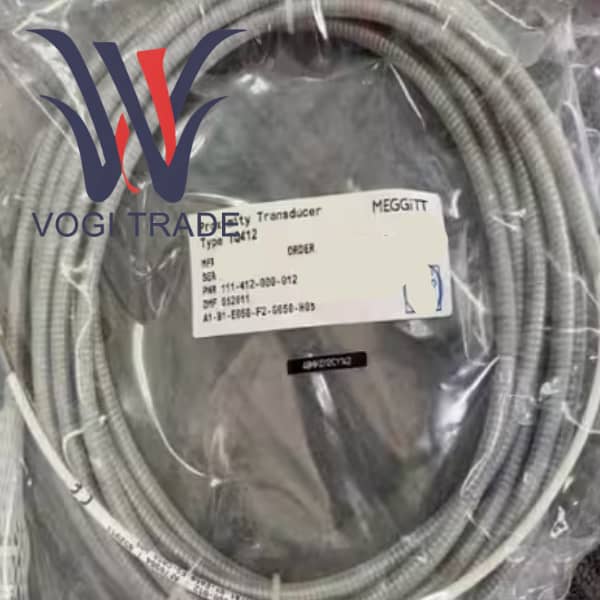
Brand: Vibro-Meter Description:Proximity Transducer Condition: New Warranty: 1 year Inventory Qty: 1 Payment term: T/T Shipping Port: Xiamen TQ412 111-412-000-012-A1-B1-E010-F1-G010-H05 is an industrial vibration monitoring module produced by Vibro-Meter, mainly used for vibration protection and monitoring of rotating machinery.
|
Manufacture |
Vibro-Meter |
|
Model Number |
TQ412 |
|
Ordering Number |
111-412-000-012-A1-B1-E010-F1-G010-H05 |
|
Catalog |
Probes & Sensors |
|
Country Of Origin |
Switzerland |
|
HS CODE |
8537109090 |
|
Dimension |
26.2cm*12.5cm*2cm |
|
Packing Dimension |
28.2cm*14.5cm*4cm |
|
Weight |
0.3kg |
Preparations Before Installation
Check the model and material
Confirm that the received sensor model is 111-412-000-012 A1-B1-E010-F1-G010-H05.
Check whether the supporting materials are complete, including TQ412 sensor (with 1m stainless steel hose), EA402 4.0m extension cable, IP 172 connection protector, and IQS900 signal conditioner.
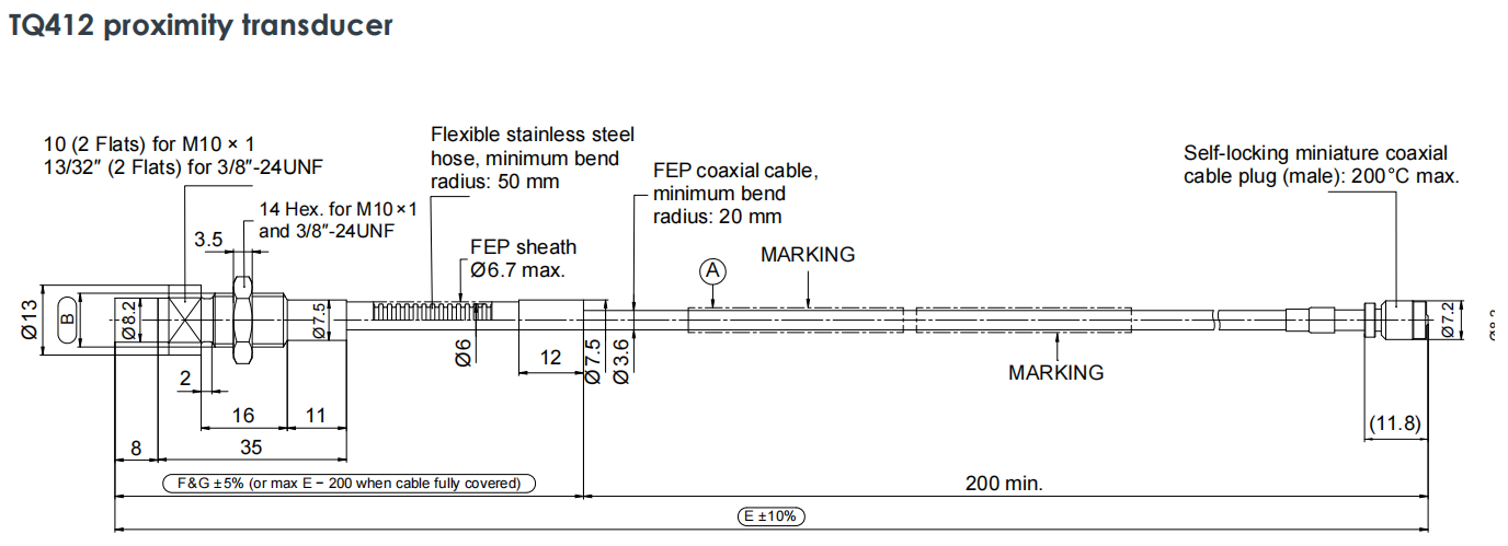
Visually inspect the flexible stainless steel hose and FEP cable of TQ412 for any indentations, cuts or deformations caused by transportation. Do not install if there is any damage.
Plan the wiring path
On the TQ412 side of the front end, plan the path from the probe installation hole to the first fixed point. This section of the path will be fully protected by F1 stainless steel hoses.
The EA402 measurement at the back end plans the path from the IP 172 protector to the control cabinet. It is strongly recommended that the EA402 extension cable be laid in a closed metal trunking, conduit or protected with a spiral wound pipe to make up for its weakness of having no flexible hose.
Sensor Installation
Probe installation
Use the appropriate wrench to screw the TQ412 into the pre-machined installation hole through the M10 x 1 thread.
The tightening torque can be referred to the manual or the standard industrial torque can be used. Do not over-tighten to avoid damaging the probe thread or the Torlon® tip.
The gap preset can adjust the initial gap between the probe and the target surface to the middle value of the range by using a feeler gauge or a special tool according to the static position of the machine shaft and the required range.
Cable laying - Key Operations:
Bending radius: 111-412-000-012 A1-B1-E010-F1-G010-H05 is strictly prohibited to bend cables with stainless steel hoses at sharp angles. The inner bending radius at any turn must be ≥ 50mm. This means that the diameter of the arc formed at the turn must not be less than 100mm. It can be achieved by using large-diameter elbow pipes or natural arcs.
Fix the cable at the following positions using wide-edge cable clamps
About 50 to 100mm behind the probe.
Fix it once every 0.5 to 1.0 meters along the wiring path.
Before entering the IP 172 protector, perform a final fixation to eliminate the pulling force.
To avoid stress, ensure that the cable is in a naturally relaxed state and do not tighten it. A certain Service Loop should be reserved to absorb the slight displacement and thermal expansion and contraction during the operation of the machine.
Connection and Protection
Connect TQ412 with EA402
Align the male end of the TQ412 integrated cable with the female end at the starting end of the EA402 extension cable.
Tighten it by hand until you hear or feel a "click" as it locks. It is strictly prohibited to forcibly tighten with tools to avoid damaging the precision self-locking micro coaxial connector.
Install the IP 172 connection protector:
Put the two halves of the IP 172 casing over the already connected joints.
Check the sealing ring to ensure that the internal rubber sealing ring is intact and correctly positioned.
Use an appropriate screwdriver to tighten the screws on the shell diagonally and evenly until the two halves of the shell are completely closed. This step is the key to ensuring that the connection point reaches the IP protection level.
System Power-on and Verification
Connect the IQS900 and attach the other end of the EA402 extension cable to the IQS900 signal conditioner.
Power on the IQS900.
Read the output
Measure the output voltage or current of the IQS900
Verification: The output value should be within the normal range, indicating that the entire measurement chain is working properly. If the output exceeds the range, the system will output a fault current, which needs to be investigated immediately.
Daily Maintenance and Troubleshooting
Regular inspections should be carried out to visually check the stainless steel hose of TQ412, the IP 172 protector and the laying path of EA402 for any new physical damage, corrosion or loosening signs.
To clean, use a clean soft cloth to wipe off oil stains or dust on the tip of the probe and the surface of the hose. Do not use organic solvents.
Common Fault Handling
In case of signal loss or abnormality, first check whether the connector within IP 172 is loose or corroded. Reinsert and make sure it is locked.
If the hose is partially flattened but the damage is not severe and does not affect the internal cables, it can continue to be observed. If the internal cable is damaged, the entire TQ412 sensor needs to be replaced.
Just disconnect IP 172 and replace it with a new 4-meter EA402 extension cable. There is no need to disassemble the already installed probe, which greatly shortens the maintenance time.