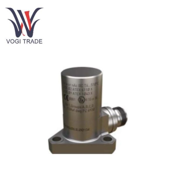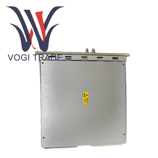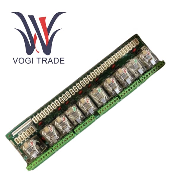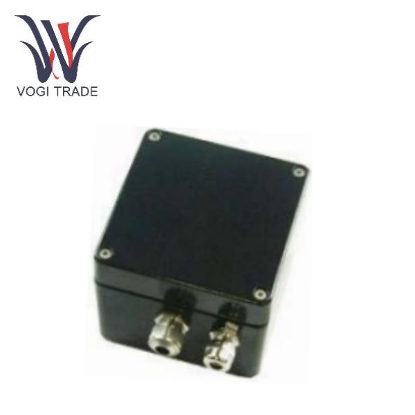
Brand: Vibro-Meter Description: Transmitter Condition: Brand New Certificate: COO TEST REPORT WARRANTY LETTER Warranty: 1 year Inventory Qty: 8 Payment Term: T/T Shipping Port: Xiamen The TWW 103 M1 is a single-channel displacement/vibration transmitter of the Vibro-Meter series under Parker Meggitt, which outputs a 4-20mA current loop signal. It needs to be matched with the WW 018 eddy current proximity sensor to achieve non-contact displacement measurement of the target object
The TWW103 M1 is a Meggitt VIbro-meter single-channel non-contact displacement transmitter. It needs to be used in conjunction with the WW018 proximity sensor to monitor the relative position of the rotating shaft. It is used for the protection and status monitoring of rotating machinery and is available in both the standard version and the Ex explosion-proof version, suitable for general and Zone 2 hazardous working conditions. The installation is wall-mounted. The length of the sensor cable is determined by ordering. When configuring, attention should be paid to the reverse characteristic of the signal. Explosion-proof models must comply with the certificate requirements. They are equipped with a built-in 5Hz low-pass and are only suitable for low-frequency displacement measurement.
|
Manufacture |
Vibro-Meter |
|
Model Number |
TWW103 M1 |
|
Ordering Number |
TWW103 M1 |
|
Catalog |
Transmitter |
|
Country Of Origin |
Switzerland |
|
Current |
100 mA max |
|
Temperature range |
0 to 70°C |
|
Weight |
0.6kg |
Product Superiority
1. Non-contact displacement conversion: Receive the signal from the WW018 proximity sensor and convert the gap displacement into a standard 4-20mA industrial current signal; When paired with the WW018 sensor, the static maximum measurement range is 10 mm, and the linear deviation is ≤2%.
2. Dual-channel isolated 4-20mA output terminal 3-4: Main output, maximum load 500Ω, used for long-term equipment monitoring; Displacement 0-10 mm corresponds to output 20-4 mA; Terminal 6-7: Auxiliary output, maximum load 25Ω, only for debugging and positioning sensors during installation; Only when terminals 3-4 are connected to a load less than 500Ω will terminals 6-7 output a signal. The two output channels are electrically isolated.
3. Fault self-check monitoring: The internal circuit continuously monitors sensor breakage, cable short circuit, and the measured target exceeding the measurement range. When a fault occurs, the analog output changes to 0mA and the red fault LED lights up simultaneously. A constantly lit green LED indicates that the equipment is operating normally.
4. Zero offset compensation: The Z potentiometer inside the casing can compensate for the position error caused by the mechanical installation of the sensor, with a compensation range of approximately ±0.5 mm.
5. Hardware filtering: 5Hz low-pass filtering, roll-off slope 20dB/tenfold frequency, mainly for static and slow-changing displacements.
6. Explosion-proof version: Ex nA non-spark protection, with ATEX, IECEx, and UKEX certifications, suitable for use in Zone 2 hazardous gas environments.
Important Notes
1. Output reverse characteristic: When the displacement is 0-10mm, the output is 20mA to 4mA, not 4-20mA which increases with the increase of the gap. Reverse conversion must be done when configuring the acquisition system.
2. Auxiliary output terminals 6-7 are not long-term monitoring outputs. Only when circuits 3-4 carry a load less than 500Ω will there be an output for terminals 6-7. They are only used for debugging sensor positioning and should not be connected to the DCS for long-term data collection.
3. The length of the sensor cable is determined upon placing an order. When replacing the sensor, it is essential to ensure that the cable lengths are exactly the same; otherwise, the measurement will be inaccurate.
4. Do not operate beyond the temperature limit; The protection level is IP66. Pay attention to the proper sealing of the cable head to ensure the protection grade.
5. Ex explosion-proof model: It is necessary to follow the special safety usage conditions specified in the original factory explosion-proof certificate. The wiring structure cannot be modified at will. It is only used in Zone2 and Ex nA non-sparking applications.
6. Fault Diagnosis: Output 0mA and a red LED light indicates a fault. The causes include: sensor disconnection, cable short circuit, and the measured target completely exceeding the measurement range.
7. The maximum compensation of the potentiometer Z is only ±0.5mm, which cannot be used to compensate for large gaps. The mechanical installation of the sensor still needs to be as accurate as possible.
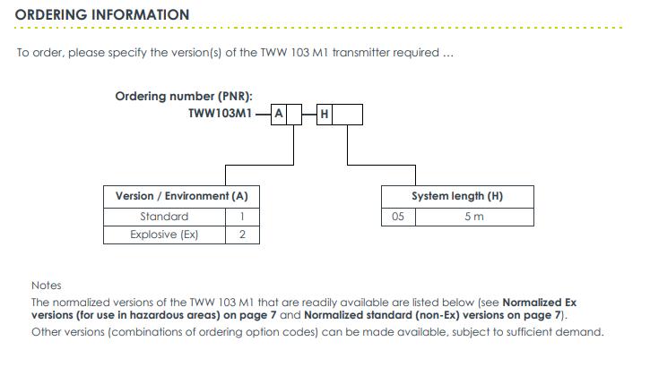
8. Order Coding rule: TWW103M1 - A* - H*; A=1 Standard version A=2 explosion-proof Ex version; H represents the cable length, and H05 represents 5 meters. Standard model in stock: Regular version TWW103M1-A1-H05; Explosion-proof version TWW103M1-A2-H05.
Supplementary: This TWW103 M1 transmitter only performs static/low-frequency displacement. It is equipped with a built-in 5Hz low-pass and is not suitable for high-frequency vibration measurement. It is suitable for monitoring slow-changing displacements such as shaft position and eccentricity.